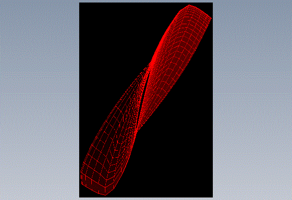
Manually Creating a 3D Blade Model
The first thing you need to do is make sure you have a smooth, and "structurally logical" blade geometry. You may need to do some manual tweaks to the geometry, and then run that geometry through more analysis to ensure there are no performance surprises.
Assuming we end up with the following blade profile (from the distribution example):
  BLADE GEOMETRY :
  ================

     X        CHORD/D   CAMBER     T/C      TWIST
    0.2000    0.1178    0.4130    0.1766   63.4999
    0.2109    0.1177    0.4325    0.1694   63.4045
    0.2507    0.1205    0.5423    0.1426   63.5477
    0.3195    0.1337    0.5985    0.1043   61.2838
    0.4071    0.1404    0.6242    0.0793   56.1779
    0.5029    0.1359    0.6491    0.0657   50.1474
    0.6000    0.1255    0.6647    0.0556   44.3321
    0.6971    0.1091    0.6852    0.0493   39.6006
    0.7929    0.0894    0.6974    0.0463   36.7073
    0.8805    0.0660    0.6998    0.0461   34.9478
    0.9493    0.0414    0.7000    0.0449   32.9863
    0.9891    0.0248    0.7000    0.0415   31.3543
    1.0000    0.0200    0.7000    0.0402   30.9520
-1- Starting with the root section (x = 0.2000, chord/d = 0.1178, camber = 0.4130, t/c = 0.1766, twist = 63.4999), plot out the airfoil coordinates and stack them at x = 0.2000. The UIUC Airfoil Data Site is a good resource for this.
-2- Get coordinates for the next section (x = 0.2109, chord/d = 0.1177, camber = 0.4325, t/c = 0.1694, twist = 63.4045) and stack them at x = 0.2109. These should also be rotated with respect to the previous section by 0.0954 degrees (i.e. 63.4999 - 63.4045).
-3- Proceed similarly with the rest of the sections. Note that you may also wish to interpolate more sections depending upon the requirements of your CFD and structural analysis software.
-4- Eventually you'll end up with a model similar to that below. Exactly how you handle/enclose the hub and tip is up to you.
